Garmin 4 Pin Power Cable Wiring Diagram
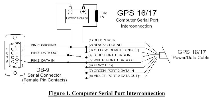
Combine helix 5 down imaging instinct bassboat fish finder portable fish finder humminbird. Solder the power/data cable data in to the transmit data (txd) pin 3 of the db9.
Garmin 172c Power Cable Wiring Diagram

Refer to the wiring diagram on pages which applies to your gps unit’s type of interface connector.

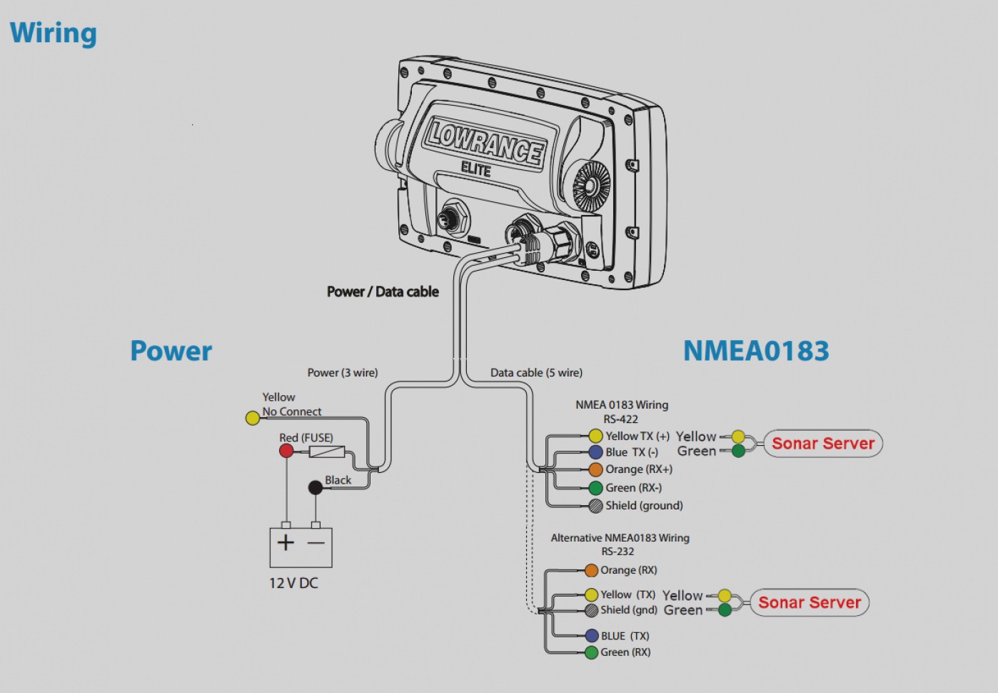
Garmin 4 pin power cable wiring diagram. Garmin striker 4 wiring diagram in addition wiring diagrams of lowrance 7 pin connector further toshiba 4 pin wiring diagram in addition 8 pin airmar transducer wiring diagram in addition garmin striker 12 volt wiring diagram as well as wiring harness for garmin fishfinder echo c furthermore wiring diagram gx24q 4 pin along with garmin. This single cable is used to provide 12v power and nmea 0183 input/output. Red with fuse to hot on battery,black to neg.
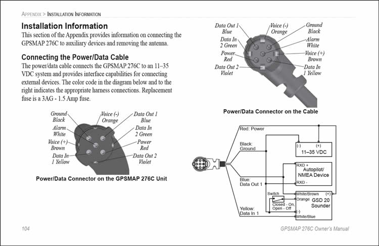
Garmin support center is where you will find answers to frequently asked questions and resources to help with all of your garmin products. The diagrams show how to correctly wire the antenna. Garmin gpsmap power and data cable used by gpsmap® 276c, gpsmap® 278, gpsmap® 296, gpsmap® 376c, gpsmap® 378, gpsmap® 396, gpsmap® 478, gpsmap® 495, gpsmap® 496 garmin nuvi gps power connector wiring diagram pinout to place garmin nuvi, oregon and gpsmap 62 gps in recharge mode.
4 pin garmin round special connector at the gps unit. Garmin power cable wiring diagram. Garmin gpsmap power and data cable pinout diagram pinoutguide com 276c 296 bare wire 8 pin cord the hull truth boating fishing forum gps to pc wiring instructions pdf free for 300i ais vhf radio nmea 0183 color help please 4x4 icon mini cooper v 421s 521s 01640 marine radar transmitter user manual wires.
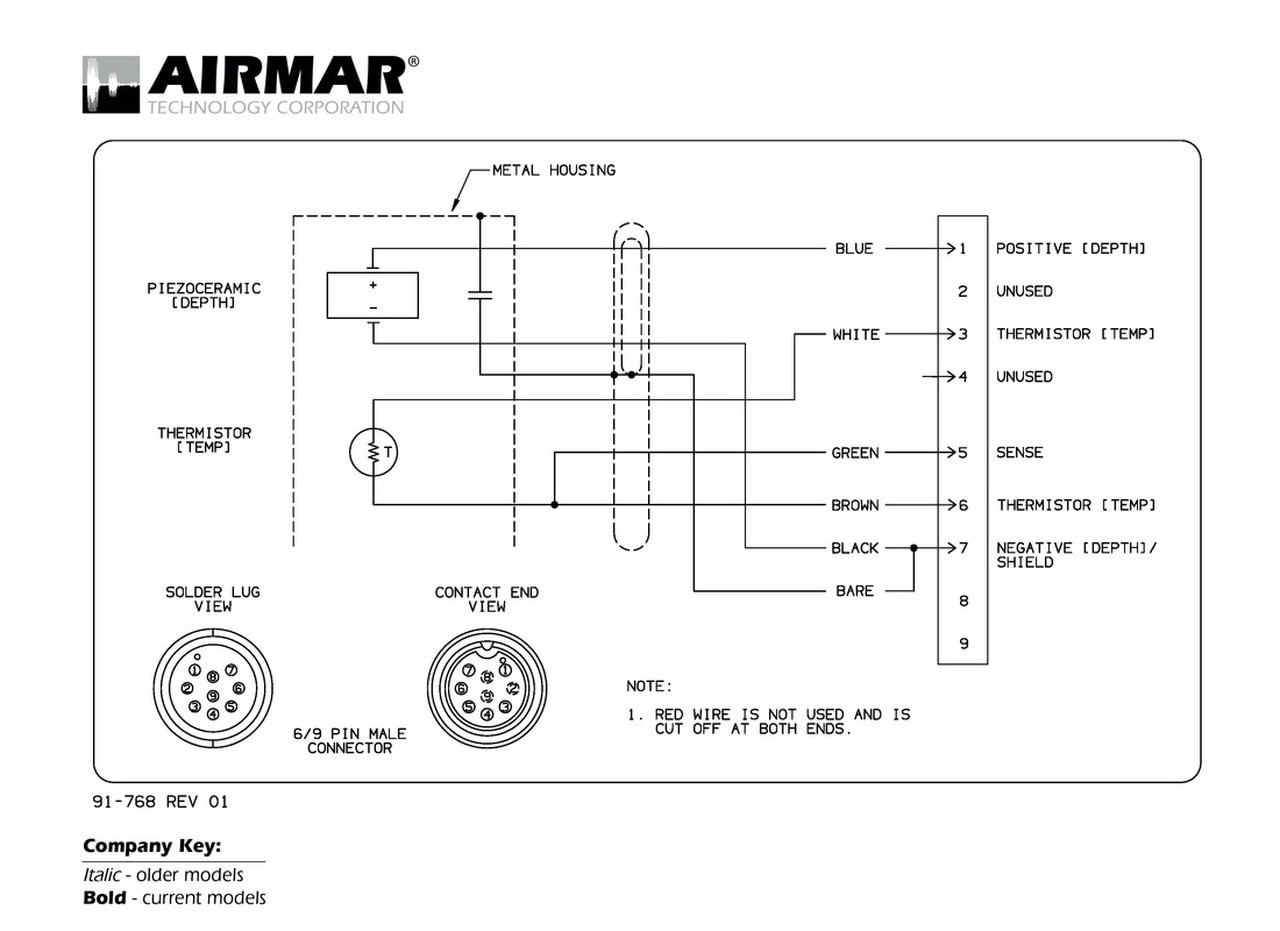
The green, white, and any other colors present have. Airmar wiring diagram garmin 6 pin (s), airmar transducer mix and match, airmar chirp transducer. Airmar wiring diagram garmin 6 pin (d), airmar transducer mix and match, airmar chirp transducer.
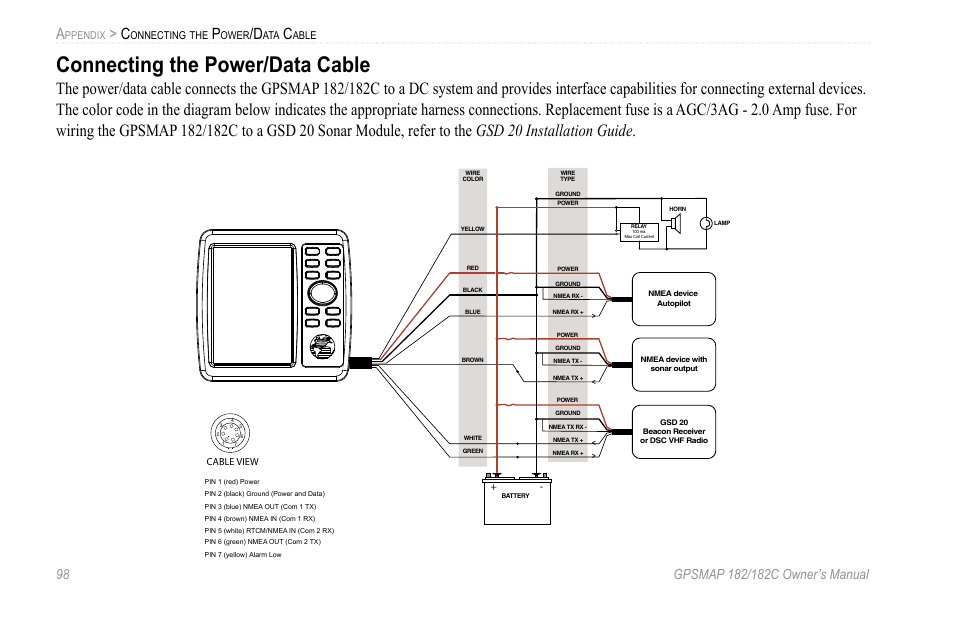
The yellow garmin wire connects to the negative end of the external alarm. Power and nmea 0183 wiring. The positive return on the alarm will connect to the red positive wire of garmin.
Solder the power/data cable data out to the receive data (rxd) pin 2 of the db9 (db25 pin 3) 4. This connector is available on: Pinouts / devices / connectors.
Garmin gpsmap power and data cable pinout. Pond king champ fish finder portable fish finder humminbird. 10 rows pinout of garmin gpsmap power and data cableused by gpsmap® 276c, gpsmap® 278, gpsmap® 296, gpsmap® 376c, gpsmap® 378, gpsmap® 396, gpsmap® 478, gpsmap® 495, gpsmap® 496.
Wiring diagram pinout to place garmin nuvi, oregon and gpsmap 62 gps in recharge mode. Bought the striker 7 sv last night and so far everything is pretty straight forward, but i do not see a wiring diagram in the box. Gamin striker 4 plus wiring in 2021 power cable power garmin.
Wire up garmin striker 4 in 2021 garmin installation instructions electrical wiring diagram The following pages contain several wiring diagrams. Solder the power/data cable data in to the transmit data (txd) pin 3.
There are no any reports for this pinout! The rst diagram on the next page is a sim ple diagram showing the gpsmap 3000 series chartplotter using the 18. Power your compatible echomap™ chartplotter/sounder combo with this 6 foot (2 meters) power/data cable.
Wiring diagram number (example ).garmin gps to pc wiring instructions refer to the wiring diagram on pages which applies to your gps unit’s type of interface connector. The wiring harness connects the device to power and nmea ® 0183 devices. Solder the power/data cable data out to the receive data (rxd) pin 2 of the db9 (db25 pin 3) 4.
The antenna must be connected to power and to a nmea 0183 compliant device. The device has one internal nmea 0183. If you are not connecting nmea 0183 devices or another chartplotter to share data, disregard the blue and brown wires.
Does anyone have a garmin pigtail wiring diagram so i can make sure i you can find the information you need in the garmin 8 pins transducer adapter manual. Solder the power/data cable data in to the transmit data (txd) pin 3 of the db9 (db25 pin 2) 5.hacking garmin etrex gps receivergarmin etrex. You may rate this document by clicking the button below.
From garmin 120 power/data cable (see diagram above for mac pin assignments): Garmin striker 4 wiring diagram, in addition wiring diagrams of lowrance 7 pin connector further toshiba 4 pin wiring diagram in addition 8 pin airmar transducer wiring diagram in addition garmin striker 12 volt. The pinout should fit these 44 devices/models.
The yellow wire is used to connect to an external buzzer or alarm to alert you to any alarms which have been set to sound on the device. Where do the go to the garmin striker 4 fishfinder with dual beam transducer webpage there are no instructions on wiring. Garmin gps 12 xl, gps ii, iii, v, 72, 76, 92, 176, 176c, 196, 295, streetpilot iii.
If the devices are mounted too far apart for the wires to reach, you can connect the devices using a user data sharing cable (). Gps connector or cable wiring scheme. You can connect up to three nmea 0183 compliant devices to receive data from one antenna.
Garmin Striker 4 Wiring Instructions
For Macintosh users
Global Positioning Systems
Garmin Striker 4 Wiring
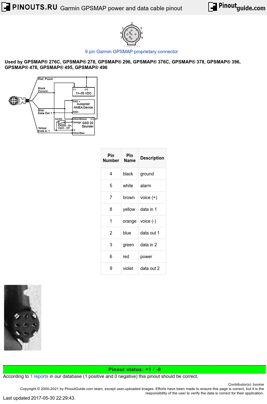
Garmin GPSMAP power and data cable pinout diagram
Garmin Striker 4 Wiring Diagram Wiring Diagram

Garmin 172c Power Cable Wiring Diagram
Garmin Striker 4 Wiring Diagram Elegant Wiring Diagram Image

Garmin Striker 4 Wiring
If it doesn’t work, try checking the following
Garmin Striker 4dv Wiring Diagram
Garmin Transducer Wiring Diagram 4 Pin Wiring Diagram Data
Garmin Striker 4 Wiring Diagram Elegant Wiring Diagram Image
Garmin Striker 4 Wiring Diagram Wiring Diagram
ANYONE HAVE OR TRIED OUT THE NEW GARMIN STRIKER 7SV Page 2

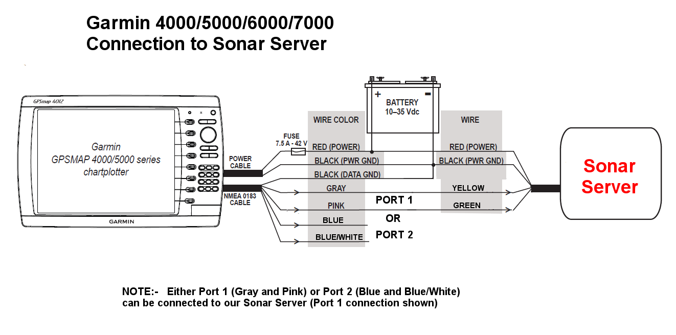
Interfacing to Garmin MultiFunction Displays Sonar Server American
Garmin Striker 4 Wiring Instructions Wiring Diagram Image
Wife lost cable for garmin 2720, need to make a temp cable, pinout? Adventure Rider
Garmin GPSmap 182c Lowrance LVR880 hookups and wiring diagram The Hull Truth Boating and